AUTOCAD’s Offset command is another of the editing tools that comprise this program and with which it is possible to create parallel lines as we will learn in this Tutorial.
You only need to select the source object, from which, with a specified distance, you can generate as many parallel objects as you want.
The Offset command creates parallel copies from source objects like lines or curves. For example, we could create concentric (parallel) circles in a single step with this AUTOCAD command.
To execute the AUTOCAD Offset command, besides selecting the source object to create the offset objects, we must specify the offset distance (or indicate it from the drawing window, with the cursor and mouse) between the source object and the copy to be created.
We must finally indicate the direction in which the offset will be performed with respect to the source.
The following figure shows the parameters involved in the execution of the AUTOCAD Offset command:

Thus, AUTOCAD’s Offset Command is executed in the following manner:
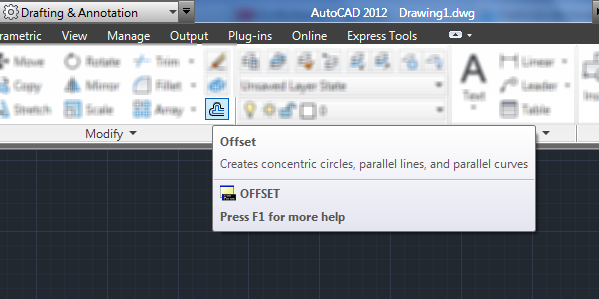
1 Select the Offset command from the Home tab→Modify panel:
2 From the Command Window (or from dynamic input if active) this message will be shown: Specify offset distance or [Through/ Erase / Layer]:
We will have several options for responding to AUTOCAD’S Offset command:
Writing the Offset Length from the reference object
Write directly from the keyboard the numerical value and press Enter or select from drawing two endpoints of an imaginary line whose length is the required offset distance.
To use the latter option it is recommended to have object Snap mode active in order to make a more precise selection of the above mentioned endpoints.
After introducing the offset distance this message will be displayed: Select object to offset or [Exit / Undo]: answer by selecting from the drawing, with mouse and cursor, the source object to be copied.
When selecting the object, the message: Specify point on side to offset or [Exit / Multiple / Undo]: will be shown, requesting us to select a point from the drawing indicating the side on which the copied object shall be created.
For example, in this tutorial’s first figure, this point would be anyone outside the area bounded by the reference object.
Selecting a point through which generated object will pass
In this case, activate the option writing the letter “T” (command line) and press Enter.
Select the object to be copied when the message Select object to offset or [Exit / Undo]: shows on commands window.
Then, when the message: Specify through point or [Exit / Multiple / Undo]: appears, select a point in the drawing area where the generated object should pass through.
This option is useful when you know where to pass the created copy but do not know the length of offset distance.
With the Layer option you can select the layer that will be assigned to the object to be created (The current or that of the reference object), by default the created object keeps the same layer that the reference object has.
To finish the AUTOCAD Offset command press the Esc key on the keyboard.